
Analog Summing Demystified – Part 1: An Introduction
Today, we are entering the dangerous territory of one of the most reliable causes for flame wars on audio forums: analog summing boxes!
It is essentially a recreation of the part of an analog mixing console that actually mixes all the channels together. The promise is to provide a bit of “console sound” while otherwise still working “in the box“. In this two-part series, we’ll analyze analog summing circuits thoroughly and try to find out what there is to it. Today’s article is about introducing you to the basics of analog summing circuits and the first of two typical types of these circuits – the passive summing network. Next week we’ll look at the active summing network and think about how we can apply what we learned to think outside the summing box.
If you follow discussions about the topic on the interwebs, there are a couple of recurring themes. My favorite claim is that the addition of many signals in the digital domain is somehow flawed and introduces errors that do not occur in analog circuits. Of course that is rather ridiculous, as of all things addition is the least problematic operation in terms of rounding. In fixed point systems, there is even no rounding at all. With floating point arithmetic, the error and the resulting signal-to-noise ratio is always lower than that of the loudest involved signal. Summing with digital arithmetics is the closest thing to perfection that we can get.
On the other hand, analog circuits are never perfect. And by never, I really mean never! Electronic circuits always suffer from noise, part tolerances, temperature sensitivity, nonlinearity, sensitivity to power supply interference, crosstalk and much more. However, well designed circuits reduce these influences to a minimum.
But such effects are not necessarily bad. The hype around analog gear we are facing is not there without a reason. Many of these unwanted side effects turn out to be a desirable quality, but by far not all of them. A little harmonic distortion, especially if it is frequency-dependent, can help tremendously in glueing signals together and thus create an improved sense of depth and homogeneity.
A new type of device that emerged over the last few years to bring some desirable qualities of analog audio equipment back to the modern world of digital audio workstations and small studios is the analog summing box. It recreates the “mixing” part of a mixing console. Being a device with a lot of inputs but only 2 outputs, it is of the more complex kind to figure out.
The Motivation
Because I often found myself misunderstood in discussions about these little boxes, let me be really clear about the reasoning behind my analysis before we get into it. First, let’s leave out the cultural discussion if someone should use an analog summing box or not. This is really a matter of taste and it depends on some more factors if your work will actually benefit from it. I want to focus on the question about how these devices affect the audio apart from just adding signals together. And I also want to zoom in on the question if there is something special going on inherent in the summing process.
The last one is very important, because a complex process where several input signals interact with each other to form an output signal would be the only thing that would be directly attributable to the summing itself. That’s where it gets interesting.
But before we get into the nitty gritty, I’d like to give you an overview about the things I don’t find interesting in analog summing boxes, and why.
Like all analog audio equipment, summing boxes will add a certain amount of noise. However, noise is (in a way by definition) unaffected by the signals involved. So we can view it separately from everything else that’s going on.
There will also be some sensitivity to power supply and ground interference (most notably mains hum). As it has nothing to do with signals as well, we’ll count that as noise.
Part tolerances and/or poor calibration will lead to slight deviations from the specified behavior. In the context of a summing circuit this will result in (very) slightly altered mixing levels and stereo pannings.
Crosstalk will also lead to (even more slightly) altered mixing levels and pannings. Especially crosstalk between the two stereo channels will lead to a slightly decreased stereo width.
These effects are already enough to make an absolutely noticeable difference when A/B testing DAW summing vs. analog summing. But it is still kind of boring, because we could just as well randomly alter faders and pots by a very slight amount and add some noise and hum to the result. And the mixing levels are even the very things we deliberately control during mixing, so that doesn’t make any sense so far.
But let’s see what else is there by having a closer look at the actual circuits involved.
Basic Analog Summing Principles
Before getting to the two fundamental types of analog summing circuits, let’s shortly recap what such a circuit must actually do. At a first glance, the task of adding a couple of signals together seems very simple. How hard can it be? Just connect all our sources to a common point and we’re done.
Unfortunately, it’s not that simple. After all, we’re talking about electronics. Let’s consider a typical application where you have several channels of a mixing desk that you want to add together. Each channel has it’s own processing, at least it will have some kind of output amplifier stage that provides the channel’s signal as a voltage at its output. If we want to transport signals as a voltage from an output to the input of another device or module, we want to make sure the output impedance of the output amplifier is low compared to the input impedance of the next device. You can think of these impedances as simple resistors, as in the picture below.
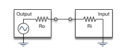
If we now just connect several sources together to a single input, the load impedance of the input will play almost no role, as from the perspective of the individual outputs, it is connected in parallel with all the (very low) source impedances of all the other channels. This will effectively short the channel output amplifiers and will lead to a lot of distortion as the amplifiers are not able to drive such small load impedances (which would result in large currents).
So for such a circuit to work correctly, we need to connect the inputs and outputs together in a way that still provides a high enough load impedance for the individual channel outputs so they can work work correctly and without distortion.
The problem can also be viewed a bit differently, by looking at the interaction between the channels. Suppose one channel outputs a positive voltage, a second one outputs a negative voltage. There will be a large voltage difference between the two channels. Along with the very low output impedances, this will lead to a large current flowing from one channel into the other. If the impedances are equal, this will indeed lead to the correct added voltage at the common terminal, but the output stages will get saturated. As a general rule: when transporting signals as voltages, we want low currents!
As mentioned before, this requirement leads to two types of analog summing circuits that are typically used: passive and active ones. At first glance they look very similar, but they work in very different ways, and have some interesting properties. So lets have a look at how these circuits work in theory.
Passive Summing Networks
Below is a schematic for the simpler type of circuit – the passive summing network.
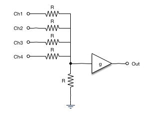
The left part of the picture shows the actual summing network. As you can see, it’s only a couple of resistors tied together. At that point, the summing part is done. The resistors are needed to prevent the individual channels from loading each other. Without these resistors, every channel would be loaded by the parallel source impedance of all other channels, which is way too low and the output will overload.
The resistor to ground shown in the picture is often not really there, it represents the input impedance of the amplifier and we assume for now that it is large compared to the summing resistors. If we go ahead and compute the signal at the summing point, we’ll see that we have successfully added all the signals together, but we also divided them by the number of channels plus the ratio of both resistors, which are usually equal. That’s why we need the makeup amplifier that is set to have a gain of 4+1=5 to boost our summed signal back to the original level.
Now let’s step back for a moment. Other than the mildly interesting properties mentioned before, what could possibly create the character we are seeking? Other than noise and imprecision due to part tolerances, we won’t get anything from the resistor network itself. What’s left is the actual makeup amplifier, which is where finally some character can be created. But this would be an effect that’s applied to the already summed signal, which is nice, but we could get the same effect by feeding an already summed signal to the makeup amplifier and thus save lots of converter channels for other purposes.
Similarly, we have the individual channel’s output stages. These can surely have some character, but at first sight it’s applied to each signal individually. Remember, keeping these amplifier stages from influencing each other is the very thing we designed the summing network for. However, a closer look at the currents in each of the inputs reveals a bit more.
Suppose there is a signal on only one of the outputs. The current it has to drive is then the current that it would drive if it were connected to just an input with equivalent input impedance. But at the common node, this current is equally distributed over the summing resistor and the individual channel resistors of all other channels. That means that in each other channel, there is a current present that depends on the channel carrying a signal.
If we now expand the picture with all channels carrying signals, we see that for each channel, added to the current that would be there if the channel were alone in the world, there is the sum of currents that all other channels drive divided by the number of channels. This is indeed a possible source for interaction between the channels, as the additional current might have some influence on the nonlinear behavior of the amplifier. But note that these additional currents are divided by the number of channels. The more channels there are, the smaller the effect would be.
If there is an actually perceivable effect depends very much on the type of amplifier stage used here. Usually, such amplifier stages have plenty of reserves to provide just a little more current without any problems. Everything else would be bad design. My guess is that in practice this is a non-issue, but being absolutely sure will require more investigation.
Now that was a very quick and dirty introduction to analog summing. If you’re not an audio electronics guru, your head might be smoking just a little bit. So I’ll let that sink in for now. This is really a challenging topic, and I have spent quite some time to figure this out. I also hope that I didn’t totally fail at the attempt to explain this stuff without throwing formulas at you and requiring you to attend Electronics 101 at a university of your choice (sorry for the schematics though). That being said, I’m sure I left out enough to fill a book. However, next week we’ll continue with the second type of summing circuit: the active summing network. And we’ll also look at how to put what we learned to best use in practice.
Until then, help me make this analysis as comprehensive as possible. If you have any questions or further remarks on this, please post them in the comments!