
Analog Summing Demystified Part 2 – Thinking Outside the Summing Box
We continue our journey through the world of analog summing with a detailed look at active summing networks. After that, we’ll recap what we now know about the analog summing myth and start thinking out of the summing box.
Before we begin, let’s recap last week’s article shortly. We started out by thinking about several possible effects that an analog summing box or an electronic summing circuit in general can have on audio. And we especially focused on the question which kinds of phenomena could actually be attributed to the summing process itself, in contrast to effects that can be considered being applied to the individual channels before summing, or applied to the already-summed result.
With this distinction in mind, we took a look at the passive summing network, which is one of the two common types of circuits used to add several signals together. In theory, this circuit performs a perfect addition, but with a signal loss depending on the number of channels. This signal loss must be compensated using a makeup amplifier. At the input side, each channel of the passive summing network must be driven by a suitable amplifier as well.
In audio electronics, things typically start to get interesting whenever some kind of amplifier is involved. This is because these amplifiers are never perfect. They might have some non-neutral frequency response and most importantly there is a nonlinearity involved which distorts the amplified signals and creates harmonic distortion. These properties are what constitutes the actual sound character of an amplifier.
So at least the channel and makeup amplifiers play a big role in defining the character of a device using a passive summing circuit. But the most important question was, is there any kind of interaction between the individual channels?
For that to happen, it is necessary that for the individual channel amplifiers, the electrical properties when connected to a summing network must be different to the connection to a normal input or load. Specifically, the signals of the other channels must be somehow visible to the channel amplifier.
For the passive summing circuit we found such a situation by looking at the currents at the channel inputs. But the influence is rather low (the lower the more channels are involved) and it is yet unclear how much this affects the behavior of an amplifier. In fact, the answer to this question will very much depend on the actual amplifier circuit used.
Active Summing Networks
With that in mind, let’s have a look at the active summing network.
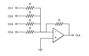
As before, the inputs are connected together through resistors, but the part that comes after the common node is different here. The triangle you see there is an operational amplifier or opamp, which is an important standard building block in electronics. It amplifies the voltage difference between its two input terminals (marked + and -) by a very large amount. In fact, the ideal version of this part would have an infinite gain!
Of course, an infinite gain is not what we want in analog electronics. But the high gain is what makes the opamp such a versatile and universal building block. It allows an opamp to serve a myriad of different purposes, be it simple amplification, filtering or in our case addition of several signals. The actual function is determined by the surrounding parts, which always include some kind of negative feedback, which means that the output of the amp is somehow routed back to the inverting input (marked -) of the opamp. As you can see, this is the case with the active summing network, too.
In the resulting circuit, the opamp does the best it can to provide an output voltage and current so that the voltage difference at the opamp inputs becomes zero. And this process happens in an instant. Now this may sound really weird, but trust me. This is actually the easiest way to think about this kind of circuits. And as before, I try to save you from having to deal with too much theory.
With that in mind, a common strategy to derive the output signal of such a circuit is to just set the voltage at the common node to 0V. This is by the way the reason why this kind of circuit is also often referred to as a „virtual ground“ summing network.
Using this trick, we can easily calculate the current that is added together from the inputs into the common node: it is the sum of the currents in each input if the resistors were connected to ground. Of course, this current has to go somewhere. It can’t go into the ground symbol, as the input impedance of the opamp is typically very high (infinite for an ideal opamp). Thus, it flows through the feedback resistor and into the output of the opamp. Current flowing through a resistor means there is a voltage across that resistor, which is our output voltage.
Now it might seem a little counterintuitive to you that this current flows into the output of the opamp and not out of it. In fact, this represents an important side effect that this circuit has: the output signals are phase inverted! However that’s no problem, since we can invert the phase again if we want at the final output stage, whatever that looks like. Or we invert the individual signals before going into the summing network.
If the feedback resistor is equal to the input resistors, and the same current flows through these, the overall gain of the circuit is 1. And you can see here that all the signals that are added together need to pass the common node and then through the amplifier. Thus, any non-ideal behavior of the opamp (such as nonlinearities) will affect the already summed output signal, just as with the makeup amplifier in the passive summing circuit from last week.
And just as we did last week, let’s finally have a look at what happens in the individual channels. Recall that with the passive summing networks, the amplifier stages driving the channels were able to „see“ a part of the signals from the other channels, which we identified as a possible, although not very likely relevant, source for interaction between the channels. The reason is that for the passive circuit, the voltage at the common node represents the summed signal, damped by the number of channels + 1.
This situation is different with the active summing network. If we would have an ideal opamp with infinite gain, the voltage at the common node would be exactly zero. In practice with a real opamp with limited gain, this is not exactly the case. But relative to the input and output signal levels, the remaining signal level measurable at the common node is lower by the actual gain of the opamp, which is typically at least 60-80 dB. This is more than enough so that this will not have any influence on the nonlinear behavior of the channel driving stages. In essence, for the channel amplifier, it doesn’t make any considerable difference if it is connected to a normal input of another device or to a virtual ground summing network.
Now What?
After all this engineering mumbojumbo lets make a quick pause and breathe deeply. I understand that this might have been tough if you are not used to thinking in circuits. However, let’s recap the results.
For both circuit types we analyzed, we were able to break the behavior down into a couple of more or less independent effects:
- As in every electronic device, we have some added unwanted noise and interference
- Due to part tolerances and crosstalk, we have a slight deviation from the ideal, which is equivalent to slightly altered level and pan settings
- Output stages of the individual channels will imprint their own character on the individual channels
- The amplifier used in the output stage will imprint its own character on the summed output signal
- There is only very little evidence suggesting an interaction between channels, especially for the active circuit
For the latter part, I can’t help but leave a little question mark there, because that will need some further investigation. In the passive circuit, the currents in each single channel contain a portion of the other signals. That shouldn’t matter much, especially when there are more than just a few channels. And if it does have an effect, it might even be very similar to what happens in the summing amp anyway. And if we were to deliberately create a configuration where this does have a significant effect, it is still very unclear if that would be a desirable quality soundwise.
But That’s Just Theory
Well you’re right. Everything that I’ve written so far does in no way tell us how it actually sounds and what the benefits are for the end result. There’s no question: if analog summing does something good to the sound, there’s no reason not to use it. My goal is something else: by trying to understand and clarify the exact behavior of such highly debated tools, I want to promote a mindful way of thinking about audio engineering. By breaking down the analog summing box into less complex building blocks, I hope to create the inspiration to fiddle around with these concepts and maybe even turn them upside down.
Now what’s also right is that this was – so far – just a theoretical analysis of analog summing circuits. The only way to confirm and find out if the remaining side effects are really as low as expected, is actual measurement. Unfortunately, measuring the exact behavior of such a complex system with multiple inputs and multiple nonlinear elements is extremely hard. Especially we have to deal with some side effects like part tolerances, that do have a significant effect on the result, e.g. when A/B comparing to a digital mix. This clearly alters the mix levels very slightly, and then it’s hard to separate this effect from the more interesting stuff that is happening when measuring or listening to it. And in fact, for altering mix levels we do have faders! I have taken part in several comparison experiments and essentially the sometimes totally different mix made it very difficult to judge the (usually very subtle) coloration and character.
Also, I have yet to figure out a strategy to comprehensively measure the exact behavior of a summing mixer. However, the quest continues. Measuring and faithfully analyzing a single nonlinear amplifier like the summing mixer is challenging enough in itself. But the good news is: we will definitely get to that right here on The Science of Sound! So stay tuned!
Thinking Outside the Summing Box
Now that we are a lot smarter with respect to the analog summing process, let’s get back to where we came from. Manufacturers of these units promise that they will get you the sound of an analog mixing console in a 1U rack unit. At the same time, this reasoning suggests that “console sound” is a matter of the process of adding signals together electronically. I think we have enough evidence as of now to doubt that. But still these units will provide part of the coloration and character from a mixing console. The funny thing is that console designers are always eager to create a console that doesn’t color or distort the sound at all. And that’s also true for summing boxes, at least the ones that don’t recreate vintage circuitry. If you want color, go for vintage, preferably with transformers in there. Otherwise you’ll probably be fine with digital summing.
On the other side of the spectrum, the only way to really get authentic vintage console sound is to use an actual vintage console, where each track goes through a full channel strip, which is much more than just an amplifier driving a summing bus. A well designed summing amplifier and a master channel strip will do the rest of glueing your mix together. All these components contribute to the sound much more than just the summing bus. Plus, working at an actual console and having every setting at your fingertips is a whole different experience than pushing a mouse around. But of course, it’s a quite big and expensive option.
If you can’t or don’t want to use a console, you won’t get that much closer by using a summing box. But you might have much more versatile options than that. You can chose a nice channel strip to treat individual tracks. Or even several different types of them if the wallet allows it. Who says that every track needs to go through the same channel strip? And you can also freely chose how to treat the master bus. You don’t even have to use hardware for that, as there are enough plugins of all types out there, and many of them do a really good job. There are even a couple of plugins that emulate the channel and bus amps of vintage consoles. And guess what, this is done by putting a channel plugin as the last effect into the individual tracks and a master plugin first in the bus channel strip. No special summing algorithm involved at all.
At this point, the little mini-series about analog summing comes to an end. I hope you enjoyed this little journey into analogland. If you can’t get enough, cry for more in the comments! For some more engineering vocabulary, check out this excellent article by Fred Forssell. And don’t forget to subscribe to my newsletter to get notified whenever fresh content is waiting for you on The Science of Sound!